Wing loading is an important parameter that has a significant effect on the performance of the air vehicles. Wings are the key components of any flying vehicle, as they produce almost all of the lift. Generally speaking, a larger aircraft will have larger wings to support its weight. For example, a Cessna C-172 has a wing area of 16.2 square meters, while the Airbus A-380 has a value of 845 square meters; however, wing loading is the prime design parameter instead of wing area.
Lift and drag are the two aerodynamic forces important in the performance calculation of aircraft. In steady and level flight, the lift requirement is equal to the aircraft weight, and drag force is balanced by the thrust of the engine or propeller. This steady condition is called the trim condition and is shown in the figure below:

Wing Loading Formula
Wing loading is defined as the ratio of aircraft weight to the reference wing area. Lift generation on the wing is proportional to the wing area, dynamic pressure of the airflow and lift coefficient which is a shape parameter. The size of the wing of an airplane is dependent on many factors, such as weight, flying speed, and the aerodynamic efficiency of the airfoil. The airfoil is the cross-section of the wing facing in to the free-stream velocity. Aerodynamic performance of the air-foil section is measured in terms of aerodynamic lift (CL) and drag (CD) coefficients. (More on the aerodynamic coefficients can be found here)

Wing Loading as a Design Parameter
For a given selection, airfoil performance and flying speed work as design criteria, and wing loading (weight/wing area) and power loading (weight/power) are the parameters that are set to achieve the desired performance. For example, the RQ-9 reaper and MOJAVE are the major attack drones, and both have a design takeoff weight of 4760kg and 3175kg, respectively. MOJAVE has a lower wing loading to achieve a lower airspeed and short field take-off and landing (STOL) requirements. A brief comparison of the design parameters of these two UAVs is shown below:
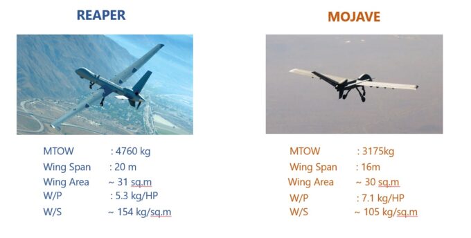
The effect of wing design of MOJAVE UAV is apparent from its ability to take-off within 300 ft; a detailed specification sheet about this aircraft can be reviewed. On the other hand, the Reaper UAV has low power loading, making it suitable for high-speed, long-endurance flights.
Sizing Trade-off Studies
The optimal way to ensure that the aircraft wing size will meet all requirements is to plot the constraint diagram. A constrained diagram with all requirements plotted will have a region of intersection of all regions where all the requirements may be fulfilled. For example, maximum speed, maximum altitude, rate of climb and stall speeds are plotted in figure below:

It is worth mentioning that desired performance can be achieved by various combinations of the sizing parameters, and the design space could be anything from a design point to a region. Most of the time, the propulsion system is already selected; in such cases, the design space is reduced to a power plant constraint line. Another is to perform a conservative sizing; in this case, a lower value of wing loading is selected so that uncertainty in weight estimation (which happens most of the time) can be accounted for.
One drawback of this approach is its higher material cost and sometimes reduced maximum speed. On the other hand, an optimistic sizing approach is to select the highest power loading, which will reduce the propulsion system size.
Impact of Wing Loading on Aircraft Performance
Since the wing loading is one of the prime contributor in the generation of lift, it has far reaching impact on the aircraft performance, stability and structural design. This is explained in following paragraphs:
Airspeed Envelope
At lower airspeeds, an aircraft with high wing loading requires a higher lift coefficient to sustain the flight, causing an increase in angle of attack (see the definition of AOA here) and an increase in lift-induced drag. Since a high value means that the surface area of the wing is lower, which is helpful in reducing the skin friction drag, which is a major source at higher airspeed. Thus, a high value of this parameter favors high speed performance, whereas a lower value favors low speed performance.
Gust Susceptibility
The low wing loading causes susceptibility to the gust condition; variation in atmospheric fluctuations causes a variation in flight path and perturbations in AOA. This causes a higher load variation, which can be uncomfortable to the passengers and even increase the loading of the wings.
Flight Performance
The flight performance of an aircraft is largely dependent on the wing loading, this is also depicted in sizing trade-off diagram. For a fixed propulsion power, a lower wing loading can enhances the STOL performance as explained in the case of MOJAVE UAV. A lower wing loading also provides a better climb performance and increases the service ceiling of the aircraft. However, a lower wing loading produces a larger wing area that increases the drag at high airspeeds, thus reducing the maximum airspeed of the aircraft.
Structural Consideration
Wing loading has a direct impact on surface area and a lower values can increase the area, which can increase wing span of the aircraft. The increase in wing span can impact structural strength on the aircraft and can also be challenging due to parking considerations.
Aircraft Wing Loading Trends
Following figure has shown the wing loading trend in three classes, general aviation , airliners and fighter aircrafts:

Finally, wing design is not only dependent on the selection of wing area but wing dimensions as well. Aspect ratio (AR) is an important parameter in making the wing more efficient; it is defined as the ratio of Wing Span to Cord Section. Aspect ratio is an aerodynamic efficiency parameter and not directly a sizing parameter; therefore, more discussion on AR and induced drag can be found here.
